FAQs | Special Offers
Di-Log frequently asked questions and special offers.
Frequently Asked Questions
Earth Leakage Measurement - New 18th Edition Regulation
How often have you spent hours fault finding Nuisance Tripping for free? Wondering, if only I knew there was an issue before I quoted for this Distribution Board upgrade?
There is a new 18th edition regulation identifying the requirement for you to measure Earth Leakage, as stated in BS7671 Reg 531.3.2. In a nutshell, each electrician must check that each install completed does not have excessive leakage to earth on each of the RCDs or RCBOs. The maximum permitted value per RCD has been set at 30% of the nominal value, i.e. a 30mA RCD would be no more than 9mA, 100mA would be 30mA and so on. Nonetheless, I am sure you would find it useful to know if there is a potential issue on an installation before you quote for your next Distribution Board change.
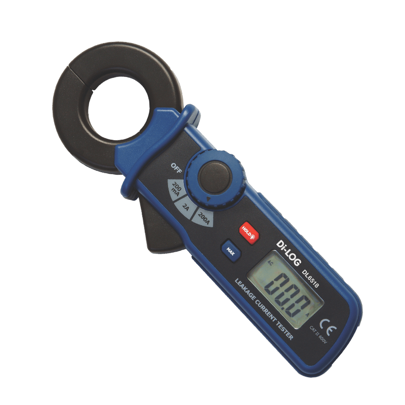
“The only way to indicate the presence of Earth Leakage would be to use an Earth Leakage Current Clamp Meter”
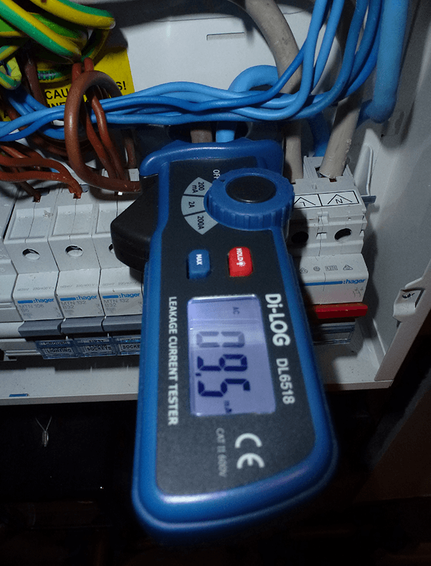
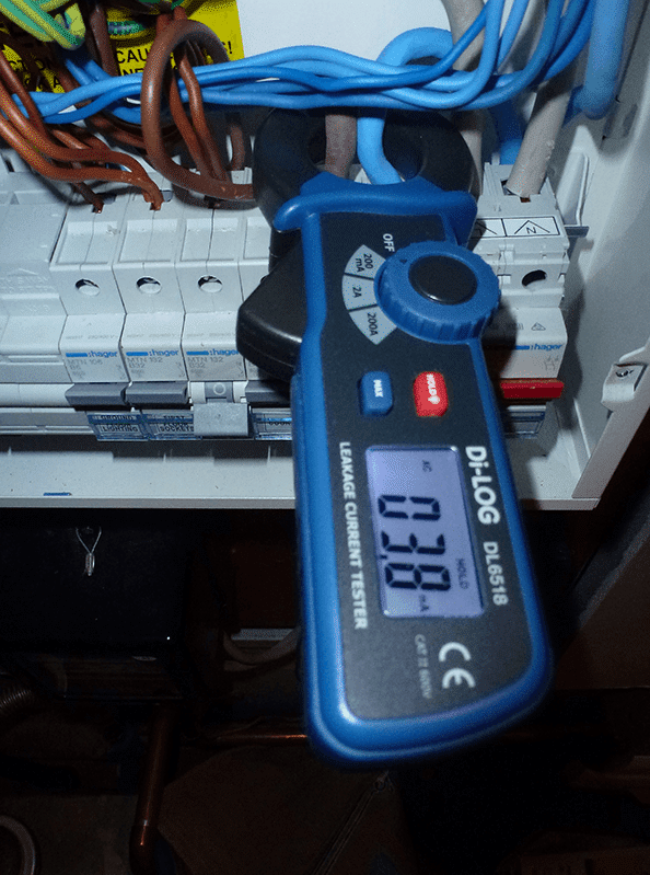
The Di-LOG DL6518 Earth Leakage Clamp is a low-cost solution that works on differential leakage measurement, which involves simultaneously clamping around the live and neutral conductors together. You can check any installation by simply clamping around your meter tails on the supply. The DL6518 has a measurement resolution of 100µA (0.1mA) making measurement very accurate when measuring minimal AC currents.
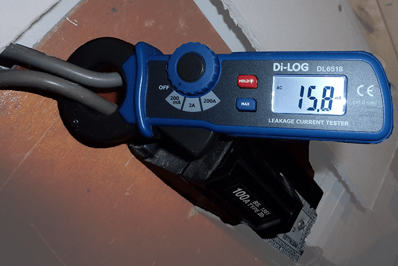
Domestic installations tend to have dual 30mA RCDs fitted or even made up entirely of RCBOs. If the installation shows a combined differential leakage current above 30% of each RCD/RCBO value, in this case 9mA, you may need to take action to manage the leakage to earth and minimise the likelihood of Nuisance Tripping. You all know how costly call outs are to any business to reset or investigate tripping RCD. Where possible, you will need to have the day to day electrical appliances in operation to accurately determine potential issues. If excessive leakage is then identified on the tails, you would then in turn need to clamp around the live and neutral conductors of each of the RCDs to determine if the leakage on that RCD is above the 30% threshold, ideally looking for a current considerably less than 9mA, repeat for each RCD.
Intentional or Unintentional Leakage
If the Earth Leakage detected on each RCD is excessive, the user will need to ask the question “Is this intentional or un-intentional?”. Intentional Earth Leakage tends to be found in electrical appliances in the form of a functioning earth, where a small amount of earth leakage is required for the appliance to function. Unintentional Earth Leakage tends to occur in poor installations where there could be a breakdown in the conductor insulation, moisture ingress, amongst many other causes.
Identification
Switching each individual circuit off, one by one is a good area to start, here you can easily identify which circuit you may need to investigate further. Once a circuit is identified, eliminate the Intentional leakage first by switching of each individual appliance one by one to see if this changes the result. Every electrical appliance has a “Protective Earth Conductor current” limit please refer to the “In service Inspection and Testing” Code of Practice for more information on these limits. If the isolating of electrical appliances does not change the result, it may well be unintentional leakage, and a check of the insulation of the conductors will be required in the form of an Insulation Test.
Leakage Management
There is an array of options to manage your Earth Leakage, balancing circuits between RCDs to fall below the 30% threshold, fitting RCBOs, Testing the electrical appliances or even a complete re-wire… all are critical when you price your next job!
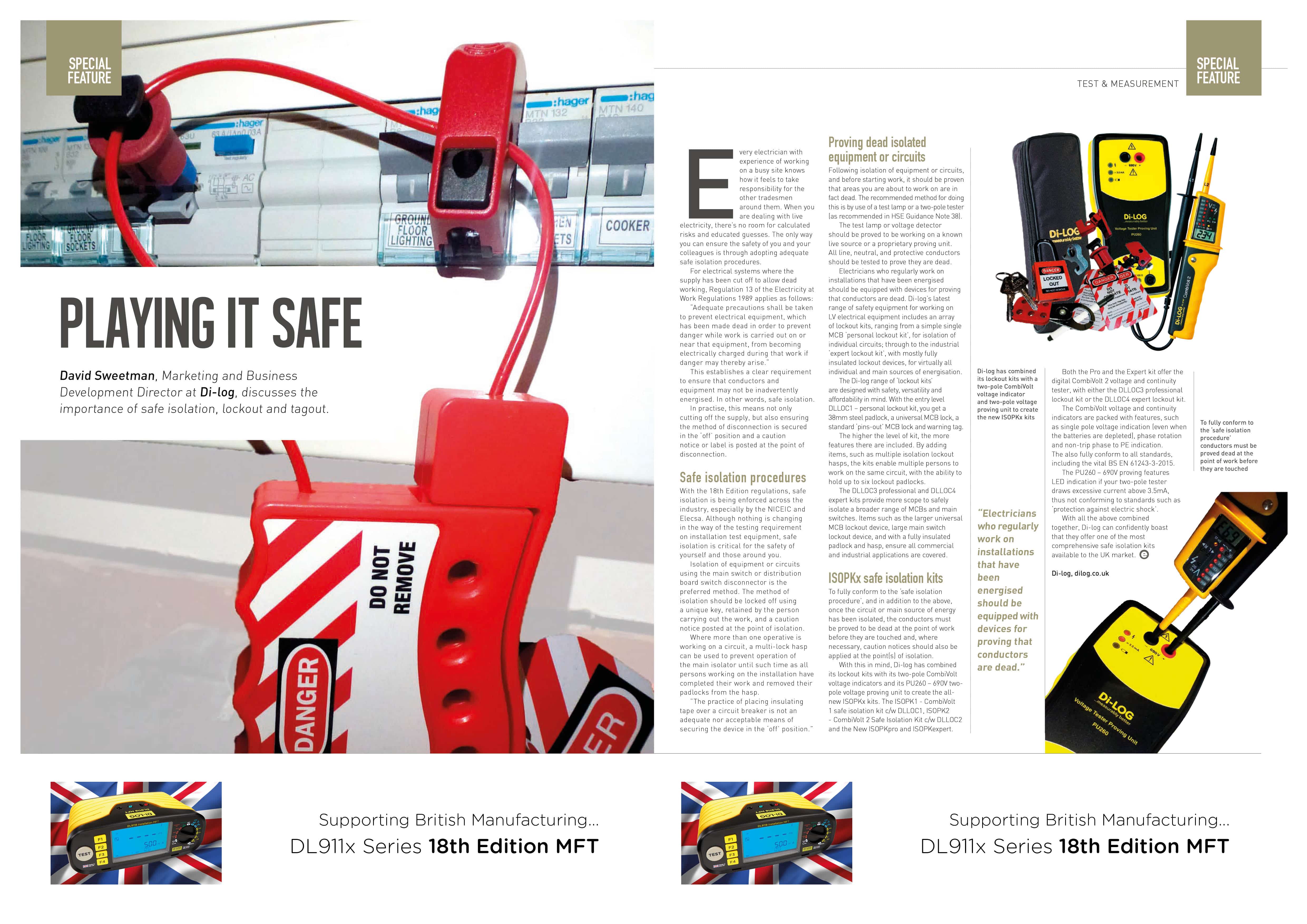
Di-log Explain the Importance of Safe Isolation, Lockout & Tagout
Lockout Tagout & Safe Isolation
David Sweetman, Marketing & Business Development Director at Di-log, discusses the importance of safe isolation, Lockout and Tagout.
Every electrician with experience of working on a busy site knows how it feels to take responsibility for the other tradesmen around them. When you are dealing with live electricity there’s no room for calculated risks and educated guesses. The only way you can ensure the safety of you and your colleagues is through adopting adequate safe isolation procedures.
For electrical systems where the supply has been cut off to allow dead working, Regulation 13 of the Electricity at work Regulations 1989 applies as follows:
“Adequate precautions shall be taken to prevent electrical equipment, which has been made dead in order to prevent danger while work is carried out on or near that equipment, from becoming electrically charged during that work if danger may thereby arise. “
This establishes a clear requirement to ensure that conductors and equipment may not be inadvertently energised. In other words, safe isolation.
In practise this means not only cutting off the supply, but also ensuring the method of disconnection is secured in the OFF position and a caution notice or label is posted at the point of disconnection.
 Click image to view full article
What Multifunction Tester should I choose?
Choosing the correct 18th Edition Multifunction tester is just one of the most important decisions you would need to make as an Electrician. The DL911x Series of MFT offer the user the choice to select which instruments suits their requirment and application. Have a look at out infographic below to help you select the right Multifunction Tester for you.

click the image to enlarge
How do I perform AutoStart Continuity R1+R2 test on the DL9118 MFT
Continuity testing on the DL9118 18th Edition MFT is very simple. The test requires the Red and Black leads to be plugged directly in to the input terminals at the top of the instrument, you will see that the terminals are clearly coloured Red & Black. Rotate the rotary dial anti clockwise to position 1. Using the correct safety equipment and qualification, remove the GS38 protective shrouds then connect the crocodile clips on to the the end of the red and black probes. With the instrument already Auto Null’d or Zero’d (Click here to watch the video on how to Auto Null your Test Leads), press the function 4 button (F4) and you will see the Auto symbol illuminate on the screen. The instrument is now set and will automatically start when it is connected to a resistive value. The DL9118 is fitted with a fully automated electronic protection system, which continuously monitors for voltage being present on any conductor. If there is any voltage in excess of 50V TRMS, the instrument will alarm, the screen will change to red and the voltage will be indicated on the screen.
To have a look at how this feature works, watch our new DL9118 in motion.
How do I measure 3 Phase Voltage Measurement on the DL9118 MFT
Three Phase Voltage Measurement on the DL9118 18th Edition MFT is very simple. The test requires all three leads to be plugged directly in to the input terminal at the top of the instrument, you will see that the terminals are clearly labeled L1 (Red), L2 (Green) & L3 (Black). Rotate the rotary dial anti clockwise the the “Volts” position. Using the correct safety equipment and qualification, connect the probes directly to the corresponding phase making sure L1 matches L1, L2 matches L2 and so on. Within seconds, the 3 phase voltage measurement is indicated on the screen of the DL9118. The 3 phase voltage measurement also includes a Phase Sequencer, which will also indicate if the phases are phased in the correct order, and subsequently will indicate how to correct incorrect phasing.
To have a look at how this feature works, watch our new DL9118 in motion.
How to perform a Non Trip Earth Loop test with the DL9118 MFT
The Di-log DL9118 has a NEW (Patent pending) method of performing a very accurate low current Earth Fault Loop Impedance measurement Zs, RCD-LOC XLT (Expert Loop Technology). RCD-LOC XLT has a unique patented noise interference and RCD uplift sensing technology which specifically looks for any characteristic which could effect the accuracy of your earth loop reading at low current.
To have a look at how this feature works, watch our now technology in motion.
My Loop Zs result should match my calculated, Ze+(R1+R2) value?
There are a lot of factors why the measured Zs results will always be higher than the calculated result, especially when an RCD is fitted for protection. Technology and IT equipment is evermore increasing in our homes and offices, creating distorted waveforms due to noise on the relevant circuits. Although manufacturers are continuously developing new methods to overcome some issues, this issue will never be eradicated. More commonly, electricians can experience RCD uplift, RDC coils are becoming ever more inductive as the market growth is driving the price of components down. Commonly, your loop measurement will always be higher due to the different method each manufacturer used to measure Earth Loop Impedance.
THERE IS A SOLUTION…

Di-log’s new low current ‘Expert Loop Technology’ RCD-LOC XLT has been 5 years in development and has now been proven to be the most accurate method to test Earth Fault Loop Impedance in a circuit which is protected be an RCD or RCBO. The RCD-LOC XLT feature is fitted in our NEW DL9118 17th Edition Multifuction Tester, click here for more information.
My inspector says I do not need annual calibration If I periodically check my meter
My Check Box replaces the need for annual calibration – FALSE
Check Boxes were more commonly introduced 2005 when Part-P was launched. The periodic meter checking process was introduced as an additional check to coincide with your annual calibration. We frequently come across electricians that have been miss fed this information by their local inspector, they may well be happy for you not to regularly calibrate your meter, but what does your liability insurance say? The guide line for all monitoring bodies is quoted to be ‘As per the manufacturer’s recommendation’ which is every year.
My Check Box replaces the need for annual calibration
Check Boxes were more commonly introduced 2005 when Part-P was launched. The periodic meter checking process was introduced as an additional check to coincide with your annual calibration. We frequently come across electricians that have been miss fed this information by their local inspector, they may well be happy for you not to regularly calibrate your meter, but what does your liability insurance say? The guide line for all monitoring bodies is quoted to be ‘As per the manufacturer’s recommendation’ which is every year.
My Meter occasionally displays >50V and inhibits the test cycle, this is a safety feature
You may well have come across a situation where your tester inhibited your test button, indicating that the contact voltage is >50V. This is a safety feature that was made mandatory when 17th edition was introduced. The RCD tester will sense if there is excessive voltage between Neutral and PE, and by injecting, for example, injecting 150mA leakage in to a 30mA RCD ( 5 x current) this could create a dangerous voltage on the earth above the safe limit of 50v.
My tester is protected when I apply mains voltage to the Insulation or Continuity function
All Insulation/Continuity Testers must be protected if mains voltage is applied to either the Insulation or Continuity Test. The applied voltage needs to be indicated, and the test button will then be inhibited. This safety feature is vital for the requirement of IEC61557 and worth checking that this feature applies to your tester.
The NEW DL9118 17th Edition MFT from Di-log has our new ‘Fully Integrated Protection System’ which electronically protects the instrument when voltage is present on any conductor during a dead test. Even if the tester is switched to Continuity Auto Mode, or you are performing an insulation test at 500V, the DL9118 is protected electronically and will alert you with a visual ‘Red Screen’ displaying the present voltage without blowing the protective fuse. Click here for more information
My continuity readings continuously reading zero when measuring R1 + R2, My meter may not necessarily be faulty?
Regularly zeroing your leads is now deemed common practice as part of your periodic checking and risk assessment protocol, with a lot of electricians expecting their leads to last the life of their test equipment. Test leads are a wear and tear items, commonly, subject to lots of stress in arduous environments with the crocodile clips deteriorating over time. The spring that connects the top toothed track to the bottom track can breakdown, causing the top track to be more resistive than the bottom. This issue really only becomes an issue if you zero your leads using the top tracks of each crocodile clip, greatly increasing your lead resistance.
Can I use my Multimeter to perform a Continuity Test
17th Edition requires your meter to inject a current >200mA to be fully conformant to IEC61557-4. Fundamentally, by injecting a larger current into a single strand cable, this greatly improves accuracy and could identify cables with poor termination.
It is normal for my meter to read results differently to a colleagues test meter
Depending on your manufacturer, each test instrument performs its own patented method to achieve a set result, especially in the case of Earth Loop Impedance. Factors that can vary, would be test current, voltage type and even frequency. Every manufacturer will try and achieve the same result, in a completely different way, with the usual effects of noise, RCD’s and interference.
Special Offers
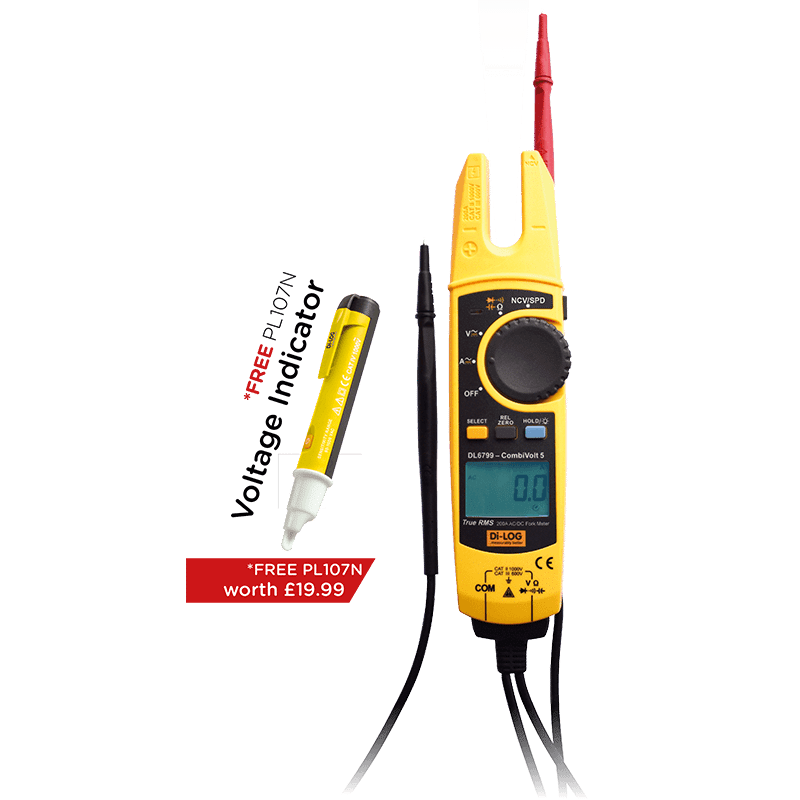
DL6799 CombiVolt 5 - Voltage, Continuity & Current Meter
The latest edition to the CombiVolt range of Voltage Testers with 200A TRMS AC/DC Current and 1000V
click image for more information
Earth Leakage Current Clamp Meter - New 18th Edition Regulation
Are you conforming to the latest 18th Edition regulations in BS7671 Reg 531.3.2?
click image for more information
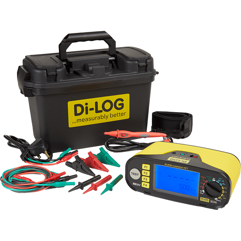
DL911x Series 18th Edition Multifunction Tester
Click here for more information on the the “British Made” DL911x Series MFT’s